ENGINYERS BCN´s BIM Library abilities
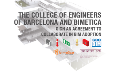
Bimetica has the opportunity to present the BIM library of Col·legi d’Enginyers Graduats i Enginyers Tècnics Industrials Barcelona (ENGINYERS BCN) aimed at fire protection. Since the beginning of March 2021, the ENGINYERS BCN BIM work group has been dedicated to analyzing the development of the library with this theme. Fire protection environment was decided due to the lack of relevant BIM objects to carry out this type of project.
The development consists of security and fire protection elements, developed with Autodesk Revit software, in IFC, and Autodesk Autocad. In addition, they were developed in 3 languages: Spanish, Catalan, and English.

After much debate and testing, it was agreed that the main objective would be make the work in fire protection projects, with BIM objects, easier for professionals. Although it may seem like an obvious principle and reference guide, in practice it was a difficult negotiation due to the diverse BIM modeling practices, the work methodologies, collaboration tipologies within the Engineers guild, and the Autodesk Revit environment. Likewise, the objects are based on the Spanish Building Technology Standard.
Based on this, the result was to develop the objects with the following bases:
- The objects will be freely positioned, without the need to base it on a wall, floor, or ceiling, to be able to work on a project with or with RVT files linked or not.
- An optimal graphical representation at a high level of detail, and a simple representation at a low level of detail.
- That the necessary connections to Mechanical, Electrical, and Plumbing (MEP) facilities be included.
- That contain the symbolic representation in plan automatically.
- That facilitate the placement in project, according to the operation of the elements.
- That they have a standardized parameter structure, incorporating the GDO-BIM Standard.
With these bases the elements were developed, with the following skills:
General Elements
Placement height
The object incorporates a parameter that will cause it to be placed, in plan view, at the minimum required height; thus facilitating its use and placement in the project.
Simbology in Plan View
Each object has its own symbology, which is suitable for its representation in plan view. It´s visible in low and medium levels of detail. Also, the user can hide the symbology using the Visible Annotation parameter. This symbol also has an editable text field, in the Text in Annotation parameter, you can also change the distance from the text to the symbol through the Distance to Text parameter.
Fire Hydrants (BIE)
Placement height
The object incorporates a parameter that will cause it to be placed, in plan view, at the minimum required height; thus facilitating its use and placement in the design.
Maximum Coverage / Separation Radius
The object incorporates a circle that indicates the coverage distance that the BIE must have. This indication helps the placing and distribution of the elements to a suitable distance. The user can edit the Visible Coverage Radius parameter to show or hide this detail. The Coverage Radius parameter can be modified, so the maximum separation between BIEs can be verified according to the project´s applicable norms.
Simbology in Plan View
Each object has its own symbology, which is suitable for its representation in plan view. It´s visible in low and medium levels of detail. Also, the user can hide the symbology using the Visible Annotation parameter. This symbol also has an editable text field, in the Text in Annotation parameter, you can also change the distance from the text to the symbol through the Distance to Text parameter.
Acess space for elements
This object has an additional geometry that represents the space that must be kept free for a person to access the element. This space has the minimum dimensions required to keep it free of obstructions. The user has the Visible Access Free Space parameter to control whether he wants to show this geometry or not. Likewise, you can also regulate the size of the space by modifying the Free Access Space parameter.
Fire extinguishers
Placement height
The object incorporates a parameter that will cause it to be placed, in plan view, at the minimum required height; thus facilitating its use and placement in the design.
Maximum Coverage / Separation Radius
The object incorporates a circle that indicates the coverage distance that the BIE must have. This indication helps the placing and distribution of the elements to a suitable distance. The user can edit the Visible Coverage Radius parameter to show or hide this detail. The Coverage Radius parameter can be modified, so the maximum separation between BIEs can be verified according to the project´s applicable norms.
Simbology in Plan View
Each object has its own symbology, which is suitable for its representation in plan view. It´s visible in low and medium levels of detail. Also, the user can hide the symbology using the Visible Annotation parameter. This symbol also has an editable text field, in the Text in Annotation parameter, you can also change the distance from the text to the symbol through the Distance to Text parameter.
Acess space for elements
This object has an additional geometry that represents the space that must be kept free for a person to access the element. This space has the minimum dimensions required to keep it free of obstructions. The user has the Visible Access Free Space parameter to control whether he wants to show this geometry or not. Likewise, you can also regulate the size of the space by modifying the Free Access Space parameter.
Fire Detectors
Maximum Visible Span
In plan, each object indicates the Maximum Visible Area by means of a circle emanating from the center of the object. The distance changes according to the selected type; Local Surface Greater than 80m2 or Local Surface Less than 80m2. The user can control the visibility through the Maximum Visible Dimension parameter in the element properties.
Visible Surveillance Surface
In plan, each object indicates the Visible Surveillance Surface by means of a shaded rectangle emanating from the center of the object. The surface changes according to the selected type; Local Surface Greater than 80m2 or Local Surface Less than 80m2. The user can control the visibility using the Visible Surveyed Surface parameter in the element properties.
Simbology in Plan View
Each object has its own symbology, which is suitable for its representation in plan view. It´s visible in low and medium levels of detail. Also, the user can hide the symbology using the Visible Annotation parameter. This symbol also has an editable text field, in the Text in Annotation parameter, you can also change the distance from the text to the symbol through the Distance to Text parameter.
Sprinkler
Plan view coverage
Each sprinkler has a rectangle in plan that indicates its coverage area. This area can be edited by the user using the Coverage Distance 1 and Coverage Distance 2 parameters.
Placement height
The object incorporates a parameter that will cause it to be placed, in plan view, at the minimum required height; thus facilitating its use and placement in the design.
Simbology in Plan View
Each object has its own symbology, which is suitable for its representation in plan view. It´s visible in low and medium levels of detail. Also, the user can hide the symbology using the Visible Annotation parameter. This symbol also has an editable text field, in the Text in Annotation parameter, you can also change the distance from the text to the symbol through the Distance to Text parameter.
Pictograms
Maximum Observation Distance
In plan, each object indicates the Maximum Distance of Observation through a vertex emanating from the object. This visual help can be hidden individually in each object, or at a general level using the Visibility and Graphics panel.
Placement height
The object incorporates a parameter that will cause it to be placed, in plan view, at the minimum required height; thus facilitating its use and placement in the design.
Simbology in Plan View
Each object has its own symbology, which is suitable for its representation in plan view. It´s visible in low and medium levels of detail. Also, the user can hide the symbology using the Visible Annotation parameter. This symbol also has an editable text field, in the Text in Annotation parameter, you can also change the distance from the text to the symbol through the Distance to Text parameter. In order to better position the symbology in plan, each object can shift its symbol to the left or right, using the Shift Right and Shift Left parameters.
We hope the elements fulfill their function and allow Engineers and other professionals in the industry to carry out their BIM activities more efficiently. It is our desire to improve the quality of work in a BIM environment, and that is why we are interested in using these objects as a starting point to model the best possible projects.
Cristóbal Bernal
Architect & BIM Content Specialist
Bimetica CTO
Contact


